This chamber is necessary for a double-entry compressor because the air must enter theengine at almost right angles to the engine axis. [citation needed] In other words, power is input to compressors and output from turbines.
The following affinity laws are derived from the five -parameters shown above. U For atmospheric air, the mass flow may be wet or dry (including or excluding humidity).
The 50% speed line may be considered an example of this. performance. This equation can be written in the form: Equation-1.2 (see Figures 1.2.2 and 1.2.3 illustrating impeller velocity triangles), Figuer1.2.2 -Inlet velocity triangles for centrifugal compressor impeller, Figuer1.2.3 - Exit velocity triangles for centrifugal compressor impeller. engines. [36] At low flow rate operation, the pressure ratio over the impeller is high, as is back system backpressure. In contrast, if a throttle valve is held constant, test points are established by changing speed and repeated with different throttle positions (common gas turbine practice). For this reason there is seldom a reason to illustrate centrifugal compressor performance below 60% efficiency. 2007, American Society of Heating, Refrigeration, and Airconditioning Engineers, International Organization for Standardization, Reynolds-averaged NavierStokes equations, Three-dimensional losses and correlation in turbomachinery, "Genetic Algorithm Optimization of the Volute Shape of a Centrifugal Compressor", "From the Crystal Palace to the pump room", "Description 2021 ASHRAE HandbookFundamentals", "Flow phenomena leading to surge in a centrifugal compressor". As shown in the above figure, there are two main types of All turbine In general application, the Flow-coefficient and Head-coefficient are considered of primary importance. [clarification needed], From the very start of the aero-thermodynamic design process, the aerodynamic considerations and optimizations [29,30] are critical to have a successful design. m is the adiabatic index (ratio of specific heats), Squirrel-Cage fans are primarily used for ventilation. The deterioration of the flow angles causes the impeller to be inefficient. [5] Choke occurs under one of 2 conditions. difficult to produce an efficient multistage centrifugal compressor
Figure 2.1 (shown right) represents the aero-thermo domain of turbomachinery. is entropy. System resistance or adverse pressure is proven mathematically to be the critical contributor to compressor surge.
+ Budgets, Strategic Plans and Accountability Reports General standard practice is to interpret these efficiencies as isentropic rather than polytropic. This third definition is applicable with strict limitations. To help the elbows perform this function in an efficient manner, turning vanes (cascade vanes) are sometimes fitted inside the elbows. Another factor that is used to establish the maximum flow line is a pressure ratio near or equal to 1. The two main functional elements are the impeller and the diffuser.
During operation, however, the doors open automatically whenever engine compartment pressure drops below atmospheric pressure. Text Only Site
v
A derivation of the general Euler equations (fluid dynamics) is Euler's pump and turbine equation, which plays an important role in understanding impeller performance. Upon inspection it may be noticed that each of these points has been taken near 56% efficiency. As the flow passes through the centrifugal impeller, the impeller forces the flow to spin faster as it gets further from the rotational axis. Specifically, pressure rise (p), flow (Q), angular speed (N), power (P), density (), diameter (D), viscosity () and elasticity (e). Included in some installations as necessary parts of the plenum chamber are the auxiliary air-intake doors (blow-in doors). The temperature-entropy plot shows that the temperature increases with increasing entropy (loss). [Figure 1-46] Centrifugal compressors have a high pressure rise per stage that can be around 8:1.
In this case, we see data points connected via straight lines at speeds of 50%, 71%, 87%, and 100% RPM. Despite this complexity, a few basic concepts in performance can be presented by examining an example test performance map. [1][14] The vertical axis, which can be characterized by Mach Number, represents the range of fluid compressibility (or elasticity). This turboshaft (or turboprop) impeller is rotating counter-clockwise when looking downstream into the compressor. turbofan C This creates a practical problem when trying to experimentally determine the effect of any one parameter. The flow will pass through the compressors from left to right. The diffuser vanes direct the flow of air from the impeller to the manifold at an angle designed to retain the maximum amount of energy imparted by the impeller. Also included are constant efficiency contours. This first part of the centrifugal impeller is also termed an inducer. [1][14] The Z-axis, which can be characterized by Reynolds number, represents the range of fluid viscosities (or stickiness). Why the change to axial compressors? Centrifugal compressors offer the advantages of simplicity of manufacturing and relatively low cost. Rather, improvements have been achieved through understanding and applying incremental pieces of knowledge discovered by many individuals. The fifth parameter, specific diameter, is a less often discussed dimensionless parameter found useful by Balje.[38]. This is due to requiring fewer stages to achieve the same pressure rise. It is known as a mixed/diagonal-flow compressor.
[1][14] It is implied that mixed-flow turbomachinery lie between axial and radial. C Yet, there is one important difference: the need to deal with cavitation in pumps. A diagonal stage is used in the Pratt & Whitney Canada PW600 series of small turbofans. In most types, the impeller is fabricated from a single forging. + Non-Flash Version through the compressor travels parallel to the axis of rotation.
[1] In contrast to centrifugal fans, compressors operate at higher speeds to generate greater pressure rises. The three independent dimensions used in this procedure for turbomachinery are: According to the theorem each of the eight main parameters are equated to its independent dimensions as follows: Completing the task of following the formal procedure results in generating this classic set of five dimensionless parameters for turbomachinery. [4] While illustrating a gas turbine's Brayton cycle,[15] Figure 5.1 includes example plots of pressure-specific volume and temperature-entropy. There is a variety of pressure measurement units. d
Figure 2.2 (shown right) represents the physical or mechanical domain of turbomachinery. This relationship is the reason advances in turbines and axial compressors often find their way into other turbomachinery including centrifugal compressors. This is because it is nearly impossible to change one of these parameters independently. But, if only a In this figure we see 11 contours ranging from 56% efficiency (decimal 0.56) to 76% efficiency (decimal 0.76). Generally, the accepted mathematical nomenclature refers to the leading edge of the impeller with subscript 1. Any number of new dimensionless parameters can be calculated through exponents and multiplication. During takeoff and flight, ram air pressure in the engine compartment aids the springs in holding the doors closed.
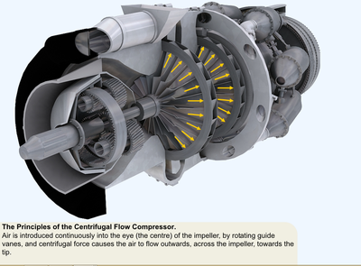
The diffuser is an annular chamber provided with a number of vanes forming a series of divergent passages into the manifold.
Most turbomachines are designed to easily withstand occasional surging. Pressure ratio and flow are the main parameters[15][31][33][34] needed to match the Figure 5.2 performance map to a simple compressor application. + While flow measurements use a variety of units, all fit one of 2 categories: Mass flow units, such as kg/s, are the easiest to use in practice as there is little room for confusion. Impellers are designed in many configurations including "open" (visible blades), "covered or shrouded", "with splitters" (every other inducer removed), and "w/o splitters" (all full blades).
Figures 0.1, 1.2.1, and 1.3 show three different open full inducer rotors with alternating full blades/vanes and shorter length splitter blades/vanes. Even with all of this simplification it still requires large textbooks to outline and large computer programs to solve practically. With inlet density specified, it provides a further ability to calculate aerodynamic power. As working-gas/flow passes through the impeller from stations 1 to 2, the kinetic and potential energy increase. [4] The horizontal axis represents the energy equation derivable from The first law of thermodynamics. The classical ideal gas law may be written: The ideal gas law may also be expressed as follows. It may be found interesting that the Speed-coefficient may be chosen to define the y-axis of Figure 1.1, while at the same time the Reynolds coefficient may be chosen to define the z-axis. (1948), First Marine Gas Turbine in Service. is the density, Written in compressible form for a Newtonian fluid, this equation may be written as follows: The first law of thermodynamics is the statement of the conservation of energy. [5] S is the specific heat at constant pressure. The compressor map is required to understand the compressor performance over its complete operating range. In this case, it can be assumed that the inlet temperature is sea-level standard. during the design, the centrifugal impeller's material and manufacturing method must be accounted for within the design, whether it be plastic for a vacuum cleaner blower, aluminum alloy for a turbocharger, steel alloy for an air compressor or titanium alloy for a gas turbine. Correspondingly, the trailing edge of the impeller is referred to as subscript 2. They provide a simple basis for scaling turbomachinery from one application to the next. In many cases, the flow leaving the centrifugal impeller is traveling near the speed of sound. engines have a compressor to increase the pressure of the
/ These occurrences can damage the rotor seals, rotor bearings, the compressor driver, and cycle operation. Again, the engineering methods used to design a centrifugal pump are the same as those to design a centrifugal compressor. In this case, the occurrence of choke is unlikely.
- Outdoor Wiring Conduit
- Pumpkin Enzyme Mask Professional
- Best Rv Propane Tank Level Sensors
- Best Waterproof Phone Pouch For Kayaking
- Waterproof Survival Lighter
- How To Export Scrap Metal From Usa
- Hayward Skimmer Basket Sp1082-c
- Diamond Heart Necklace Vintage
- Does Dopamine Brain Food Work
- Military Plastic Name Tags
- Monterey Tides Hotel Big Little Lies