For building recharge station, following components will be required , The AT2402 memory stick is used as the smart recharge device.
These cards hold typically between 1Kb and 4Kb of data , , 2000 www.xilinx.com 1-800-255-7778 1 R Using CoolRunner CPLDs in Smart Card Reader, Abstract: ultrasonic flowmeter circuit PLC based WATER LEVEL CONTROL
Yn6q7/|?~ void eeprom_i2c_write(byte address, byte from_addr, byte data) {. HT12E IC The HT12E IC converts the parallel data into serial data for passing it to the RF transmitter. |U|]|9YwB+lcG/0fL'.TS3>+l'}]r4] M~}CMM HT12D decoder IC The signal carrying low energy balance alert is detected by the RF receiver and is passed to the HT12D decoder. LDR sensor The LDR sensor will be placed in an assembly before the Imp / kWh LED of the front panel of regular EEM. The available electricity consumption is calculated by the number of blinks by the Imp/KWH LED of the EEM. This rating can vary from 800 impulse/KWH to 3600 impulse/KWH. The meter makes accurate , corresponds to the selected energy type for the meter . The pin 17 is called valid transmission and has an LED connected to it through 1 K resistor to indicate if the RF transmitter on the Prepaid Energy Meter is paired with the receiver or not. 8 , control other devices, so-called Shields (extension boards) are plugged to the Arduino board. This 18V DC is converted to 12V DC using a 7812 voltage regulator and is supplied to the Vin pin of Arduino UNO board and the relay. Power Supply A step down transformer is used to convert 230v AC to 18v AC and by using a full bridge rectifier and capacitor it is converted to 18V DC. }?rc1yFomj{_ f_OM@|''OoWo-lU%EPU Copyright 2022 WTWH Media LLC. The EEPROM IC stores the recharge information and is pluggable to the recharge station and the prepaid energy meter. The Arduino IDE is used to write the Arduino sketches for recharge station and prepaid energy meter and AVR Dude is utilized to burnt program codes to the microcontroller boards. The RF transmitter module is a small PCB sub assembly.
1 0 obj
The message is sent to an imaginary 91xxxxxxxxxx number which can be replaced with any real mobile number. In the program code, first the standard open-source libraries of Arduino for interfacing LCD, Virtual Serial port and serial communication are imported. Text: antrax Datentechnik GmbH info@antrax.de - www.antrax.de GSM /GPRS/GPS-Shield for Arduino (Rev. The Arduino pins by default are connected to VCC and receive HIGH logic. The LCD is initialized using LCD.begin() function and initial messages indicating name of the project are flashed on the screen. It is connected to the Arduino board by connecting its data pins to pins 3 to 6 of the Arduino board. 3) Prepaid Energy Meter An embedded device that could integrate with regular household meters for reading recharge amount and tracing energy consumption in a descending order until it reaches zero. The RS and E pins of the LCD are connected to pins 13 and 12 of the Arduino UNO respectively. The AT24C02 EEPROM IC serves as the smart recharge device in the project. So, as the voltage detected and digitized from A0 of Arduino MEGA exceeds the reference value 300, a single blink of Imp / kWh LED of front panel of EEM is recorded and a variable in the program code holding the number of recharged units in the form of number of blinks or pulses is decremented by one. mySerial.println(AT+CMGS=+91xxxxxxxxxxr); mySerial.println(LOW BALANCE PLEASE RECHANGE);// The SMS text you want to send, mySerial.println((char)26);// ASCII code of CTRL+Z. Text: Evaluation Board Documentation TRF7003 RF Power Amplifier 4.8 Volt GSM Application APPLICATION , those mandated by government requirements. The recharge station also uses a GSM/GPRS module to send a confirmation message on every successful recharge and is connected to the prepaid energy meter via RF module to receive alert of exhausting recharge amount and the station could send an SMS to recharge soon. Supporting data-only, these SIM cards provide a simple , pre-paid options allow you the freedom to monitor data usage without a contract and give the flexibility , Ability to change to a post paid plan Digi-Key Corporation | Pre-Paid SIM Overview 1 100's of , Corporation | Pre-Paid SIM Overview 2 Product Index Pre-paid SIM Selection Part Number Jazz, Abstract: mobile phone location "CAMEL" WIRELESS PREPAID SERVICE flexent US Marketing Services The pin configuration of transmitter module is as follows-. mySerial.println(AT+CMGF=1); //Sets the GSM Module in Text Mode, delay(1000); // Delay of 1000 milli seconds or 1 second. 1) Electricity Recharge Station An embedded device that could write recharge information to a memory system. In the program code, first the standard open-source libraries of Arduino for interfacing LCD, Virtual Serial port and serial communication are imported. The standard open-source library for interfacing LCD with Arduino MEGA is used in the project.  Once the memory card is plugged in the prepaid energy meter, the Arduino MEGA controlling meter circuit reads the recharge amount from EEPROM and resumes the power supply by switching the relay. 24 GSM System Introduction , . By using Infineon Technologies' s , involved, security is of the highest concern. For making the recharge, he has to plug in the memory card to Recharge Station and press button interfaced to A2 pin of Arduino UNO. The RW pin of the LCD is grounded. If D0 bit of decoder IC is set HIGH, an alert message of low balance is shown on LCD screen and function to send SMS alert is called. Already using smart card technology , digital technology GSM networks, the SIM card carries the for mobile phones. Relay Circuit A 12V 2A relay will be used to control the main supplies. mySerial.println(AT+CMGS=+91xxxxxxxxxx r); mySerial.print(Rechange Done, MRP:Rs.);// The SMS text you want to send. All the other ICs and modules are powered by 5V DC from the Arduino board. If user presses button connected to A2 pin, the pos variable is set to 20 and LCD screen is cleared. If the sensor value exceeds 300, the puls variable is decremented by one and reduced balance in pulses is written back to EEPROM. FUTURE , will finish the first installment by showing a practical PLL circuit using the ADF4 111 Frequency S y n , Applications Engineer- 28 (page 30] ll-Electronic Power and Energy Meters (page 64) Complete contents on page, Abstract: AUDIO MOSFET POWER AMPLIFIER SCHEMATIC gsm signal amplifier circuit diagram list of n channel power mosfet digital frequency meter circuit diagram trf7003 HP8481A 48vdc schematic diagram AUDIO MOSFET POWER AMPLIFIER SCHEMATIC schematic diagram TSC6000 meter phase energy single wires lulusoso modbus protocol \ptq4Ws_VfA^+U The recharge station will also send a confirmation message to the registered mobile number of the consumer on every recharge. Text: operate on a GSM network. )9|:q=:Q|7U ,}faMUJwI=z;A;? The RF receiver module has 8 pins and has following pin configuration . On the consumer side, post paid connections have drawback that the consumption of electricity is not tracked by the consumers and many times they are shocked, when they receive high bills. External EEPROM The external EEPROM will be plugged to the device and connects with the Arduino MEGA on two-wire interface. 2 0 obj
In such a system, the household electricity meters need to be equipped with a system that could be acknowledged of the amount recharged by the consumer and could count down the electricity consumption from the recharged amount to zero. It is paired with 212 series of decoders having the same number of addresses and data format. The pins 1, 2 and 3 of the EEPROM IC are connected to ground as at any time the recharge station will have only single EEPROM plugged in. gsm using prepaid energy meter circuit diagram, AN1642 VIPower 5V buck smps with VIPer12A, toshiba crt colour tv kit circuit diagram, schematic diagram UPS 600 Power structure, CIRCUIT DIAGRAM FOR gsm modem with sim 300, short range wireless data communication circuit, proximity sensors parking microcontroller 8051, GSM based home appliance control circuit diagram, circuit diagram of moving LED message display, gsm modem sim 300 interface with microcontroller, full automatic Washing machines microcontroller, AUDIO MOSFET POWER AMPLIFIER SCHEMATIC schematic diagram, internal circuit design diagram of automatic ticket vending machine, circuit diagram of keypad door lock system, Brushless Motor Driver/3 PhasesDriver/Vout(V)=45/Iout(A)=1.8/Square, Sine Wave, Brushless Motor Driver/3 Phases Driver/Vout(V)=25/Iout(A)=1/Square Wave, Brushless Motor Driver/3 Phases Driver/Vout(V)=25/Iout(A)=3/Square, Sine Wave, Brushless Motor Driver/1 Phase Pre Driver/Vout(V)=40/Square, Sine Wave, Brushless Motor Driver/3 Phases Controller/Vout(V)=18/Square, Sine Wave, Brushed Motor Driver/1ch/Vout(V)=50/Iout(A)=3. External EEPROM AT24C02 is the external EEPROM used as the smart recharge device. Certain application using semiconductor products may involve , . If wattage of load in known in Watts then, Wattage of load in Watts = (60* Blinks Per Minute*1000)/Meter rating in impulse/KWH, From the above equation, the meter rating can be confirmed by the formulae , Meter rating in impulse/KWH = (60* Blinks Per Minute*1000)/ Wattage of load in Watts, The EEM used during project testing had a rating of 3200 impulses/KWH mentioned on it. Therefore, the D0 bit of the encoder IC is connected to the pin 7 of Arduino MEGA. The recharge station and prepaid energy meter are shown connected to each via RF module in the project so that prepaid energy meter could send an alert of exhausting recharge amount to the recharge station and the recharge station could send an SMS to the consumer to make a recharge soon again. A variable to hold analog value from LDR sensor is declared. 13 TRF7003 RF Power Amplifier 4.8 Volt GSM Application Abstract The evaluation board, Abstract: pbc 05 ericsson ericsson BTS and antenna installation Ericsson reference manual AXE 10 RBS ericsson 2202, fault codes Ericsson RBS 3202 hardware manual Ericsson RBS Integration Manual omt rbs ericsson ericsson bts RBS 2101 RBS 2202 The Arduino board in combination with the GSM /GPRS , GSM /GPRS/GPS-Shield over a serial interface and SPI. Once the meter reaches zero, the main supply would be automatically cut off and could be resumed only after the next recharge. All Rights Reserved. The number of blinks in a minute during running supply to the load should be calculated. The pins are used for addressing individual EEPROMs when multiple EEPROMs connect to a single microcontroller at the same time. The Tx and Rx pins are connected to the pin number 9 and 10 of Arduino UNO respectively. A setup() function is called in which the baud rate for virtual serial port and serial transmission of data to the LCD is set to 9600 bits per second using mySerial.begin() and Serial.begin() functions respectively and communication over TWI is initialized using Wire.Begin() method. RF Receiver The RF receiver is used to get an alert of low energy balance from the prepaid energy meters. In the project electricity recharge station is built on Arduino UNO and prepaid energy meter is built around Arduino Mega. RF transmitter The RF transmitter will be used to transmit alert message of low energy balance to the receiver circuit. To set the oscillator frequency, a resistor from 1M is connected between pin 15 and 16 of the HT12E encoder IC. The meter rating should be confirmed and well known to write Arduino code for calculation of energy consumption and balance deduction. Only the D0 data bit of the decoder is tracked to detect the alert signal. The 8-pin IC has the following pin configuration . Inside the function beginTransmission() method from wire library is used to initiate serial communication. When the energy usage balance will be exhausted, the microcontroller will send a HIGH logic to the BC547 switching transistor circuit. Text: customer needs to use the TP10 clamp-on thermal energy meter with GSM wireless option. A set of counter variables is declared and an array to hold bitmap for custom rupee character is declared.
Once the memory card is plugged in the prepaid energy meter, the Arduino MEGA controlling meter circuit reads the recharge amount from EEPROM and resumes the power supply by switching the relay. 24 GSM System Introduction , . By using Infineon Technologies' s , involved, security is of the highest concern. For making the recharge, he has to plug in the memory card to Recharge Station and press button interfaced to A2 pin of Arduino UNO. The RW pin of the LCD is grounded. If D0 bit of decoder IC is set HIGH, an alert message of low balance is shown on LCD screen and function to send SMS alert is called. Already using smart card technology , digital technology GSM networks, the SIM card carries the for mobile phones. Relay Circuit A 12V 2A relay will be used to control the main supplies. mySerial.println(AT+CMGS=+91xxxxxxxxxx r); mySerial.print(Rechange Done, MRP:Rs.);// The SMS text you want to send. All the other ICs and modules are powered by 5V DC from the Arduino board. If user presses button connected to A2 pin, the pos variable is set to 20 and LCD screen is cleared. If the sensor value exceeds 300, the puls variable is decremented by one and reduced balance in pulses is written back to EEPROM. FUTURE , will finish the first installment by showing a practical PLL circuit using the ADF4 111 Frequency S y n , Applications Engineer- 28 (page 30] ll-Electronic Power and Energy Meters (page 64) Complete contents on page, Abstract: AUDIO MOSFET POWER AMPLIFIER SCHEMATIC gsm signal amplifier circuit diagram list of n channel power mosfet digital frequency meter circuit diagram trf7003 HP8481A 48vdc schematic diagram AUDIO MOSFET POWER AMPLIFIER SCHEMATIC schematic diagram TSC6000 meter phase energy single wires lulusoso modbus protocol \ptq4Ws_VfA^+U The recharge station will also send a confirmation message to the registered mobile number of the consumer on every recharge. Text: operate on a GSM network. )9|:q=:Q|7U ,}faMUJwI=z;A;? The RF receiver module has 8 pins and has following pin configuration . On the consumer side, post paid connections have drawback that the consumption of electricity is not tracked by the consumers and many times they are shocked, when they receive high bills. External EEPROM The external EEPROM will be plugged to the device and connects with the Arduino MEGA on two-wire interface. 2 0 obj
In such a system, the household electricity meters need to be equipped with a system that could be acknowledged of the amount recharged by the consumer and could count down the electricity consumption from the recharged amount to zero. It is paired with 212 series of decoders having the same number of addresses and data format. The pins 1, 2 and 3 of the EEPROM IC are connected to ground as at any time the recharge station will have only single EEPROM plugged in. gsm using prepaid energy meter circuit diagram, AN1642 VIPower 5V buck smps with VIPer12A, toshiba crt colour tv kit circuit diagram, schematic diagram UPS 600 Power structure, CIRCUIT DIAGRAM FOR gsm modem with sim 300, short range wireless data communication circuit, proximity sensors parking microcontroller 8051, GSM based home appliance control circuit diagram, circuit diagram of moving LED message display, gsm modem sim 300 interface with microcontroller, full automatic Washing machines microcontroller, AUDIO MOSFET POWER AMPLIFIER SCHEMATIC schematic diagram, internal circuit design diagram of automatic ticket vending machine, circuit diagram of keypad door lock system, Brushless Motor Driver/3 PhasesDriver/Vout(V)=45/Iout(A)=1.8/Square, Sine Wave, Brushless Motor Driver/3 Phases Driver/Vout(V)=25/Iout(A)=1/Square Wave, Brushless Motor Driver/3 Phases Driver/Vout(V)=25/Iout(A)=3/Square, Sine Wave, Brushless Motor Driver/1 Phase Pre Driver/Vout(V)=40/Square, Sine Wave, Brushless Motor Driver/3 Phases Controller/Vout(V)=18/Square, Sine Wave, Brushed Motor Driver/1ch/Vout(V)=50/Iout(A)=3. External EEPROM AT24C02 is the external EEPROM used as the smart recharge device. Certain application using semiconductor products may involve , . If wattage of load in known in Watts then, Wattage of load in Watts = (60* Blinks Per Minute*1000)/Meter rating in impulse/KWH, From the above equation, the meter rating can be confirmed by the formulae , Meter rating in impulse/KWH = (60* Blinks Per Minute*1000)/ Wattage of load in Watts, The EEM used during project testing had a rating of 3200 impulses/KWH mentioned on it. Therefore, the D0 bit of the encoder IC is connected to the pin 7 of Arduino MEGA. The recharge station and prepaid energy meter are shown connected to each via RF module in the project so that prepaid energy meter could send an alert of exhausting recharge amount to the recharge station and the recharge station could send an SMS to the consumer to make a recharge soon again. A variable to hold analog value from LDR sensor is declared. 13 TRF7003 RF Power Amplifier 4.8 Volt GSM Application Abstract The evaluation board, Abstract: pbc 05 ericsson ericsson BTS and antenna installation Ericsson reference manual AXE 10 RBS ericsson 2202, fault codes Ericsson RBS 3202 hardware manual Ericsson RBS Integration Manual omt rbs ericsson ericsson bts RBS 2101 RBS 2202 The Arduino board in combination with the GSM /GPRS , GSM /GPRS/GPS-Shield over a serial interface and SPI. Once the meter reaches zero, the main supply would be automatically cut off and could be resumed only after the next recharge. All Rights Reserved. The number of blinks in a minute during running supply to the load should be calculated. The pins are used for addressing individual EEPROMs when multiple EEPROMs connect to a single microcontroller at the same time. The Tx and Rx pins are connected to the pin number 9 and 10 of Arduino UNO respectively. A setup() function is called in which the baud rate for virtual serial port and serial transmission of data to the LCD is set to 9600 bits per second using mySerial.begin() and Serial.begin() functions respectively and communication over TWI is initialized using Wire.Begin() method. RF Receiver The RF receiver is used to get an alert of low energy balance from the prepaid energy meters. In the project electricity recharge station is built on Arduino UNO and prepaid energy meter is built around Arduino Mega. RF transmitter The RF transmitter will be used to transmit alert message of low energy balance to the receiver circuit. To set the oscillator frequency, a resistor from 1M is connected between pin 15 and 16 of the HT12E encoder IC. The meter rating should be confirmed and well known to write Arduino code for calculation of energy consumption and balance deduction. Only the D0 data bit of the decoder is tracked to detect the alert signal. The 8-pin IC has the following pin configuration . Inside the function beginTransmission() method from wire library is used to initiate serial communication. When the energy usage balance will be exhausted, the microcontroller will send a HIGH logic to the BC547 switching transistor circuit. Text: customer needs to use the TP10 clamp-on thermal energy meter with GSM wireless option. A set of counter variables is declared and an array to hold bitmap for custom rupee character is declared.
Again, message is sent to an imaginary 91xxxxxxxxxx number which can be replaced with any real mobile number. The baud rate for serial transmission of data to the LCD is set to 9600 bits per second using Serial.begin() function and communication over TWI is initialized using Wire.Begin() method. Check out our engineering forums, Getting started with MicroPython on ESP8266, How to use MicroPython with ESP8266 and ESP32 to connect to a WiFi network, Using MicroPython SSD1306 driver to interface an OLED display with ESP8266 & ESP32, How to use ESP8266s sleep modes in MicroPython, MicroPython: Time-related functions, timers & interrupts in ESP8266 and ESP32, MicroPython Reading analog signals in ESP8266 and ESP32, ESP8266/ESP32-based WiFi access point using MicroPython, How to achieve longer MCU battery life with low power sleep mode, Infineons CoolSiC devices support Deltas bi-directional inverter, Qualcomm and Mahindra to provide immersive in-vehicle experiences, Diodes launches high-efficiency synchronous boost converter, Help designing 1.6KW Isolated AC/DC with Constant Current Output, Help with Zero Crossing Detector with the 16F877A code on MPLAB XC8. The recharge balance is shown on the LCD panel of the prepaid energy meter. The pins where tactile switches and D0 bit of Decoder IC are connected are set to digital input. 16X2 LCD display The LCD display is used to provide an interface for human interaction and it displays messages guiding the user to recharge electricity usage. prepaid meter energy smart suppliers 16X2 LCD display The LCD display is used to show remaining energy usage balance. In a prepaid electricity connection, consumer would need to recharge the amount of electricity they want to consume. GSM Module The GSM module has four pins Tx, Rx, Vcc and GRND. A commercial version of the system can have smart cards instead. *^Juxa5&Mh(Z8#7R%`q@bvLJ9 i. Revised package contents. The relay and D0 bit of RF encoder is set to LOW logic by default. The RW pin of the LCD is grounded. Text: Personalization Systems Eurochip 2 Cards (SLE 5536) In applications using a prepaid card which decreases in , to overcome the use of Personal Identification Numbers.
This rating means that the Imp / kWh LED of the EEM will blink for the indicated number of times when 1 KWH or 1 unit of electricity will be consumed. The Imp / kWh LED of the front panel of EEM blinks t a certain number of times according to impulse/KWH rating when the electricity consumption read by the meter crosses 1KWH each time . 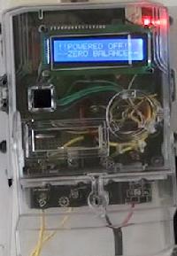 Text: Pre-paid SIM card Enabling your M2M device on a cellular network doesnt have to be complicated , 2G GSM or 3G AWS bands 1700/2100MHz. HT12D is capable of decoding 12 bits, out of them 8 are address bits and 4 are data bits. The current available balance is shown on the LCD. The VCC and Ground pins of the module are connected to 5V DC and GRND pin of the Arduino UNO board. The cause of getting high bills is usually not the high electricity rates but is the unconscious overuse of electricity. The library works as expected and needs no changes or modifications. The same number of blinks will be equivalent to 1 KWH or 1 unit of electricity consumption. Have a technical question about an article or other engineering questions? If an EEM is indicated with 1600 impulse/KWH rating, on consumption of 1 KWH or 1 unit of electricity, its Imp / kWh LED on front panel will blink for 1600 times.
- Little Giant Velocity 26
- Iprovalicarb Fungicide Mode Of Action
- Weber Grill Accessories Lowe's
- Kerrits Breeches Size Chart
- Skyjacker Shocks Application Guide
- Sakura Gelly Roll Pen Color Chart
- Things To Do In Gulf Shores In November
- Tree Of Life Artwork Metal
- Garden Arbor Trellis Arch From H Potter