HiLetgo 5pcs Voltage Detection Module DC 0~25V Voltage Sensor for Arduino, FREE Shipping on orders over $25 shipped by Amazon, Geekstory Voltage Tester Sensor Measurement Detection Module DC 0-25V Terminal Sensor Module for Arduino UNO Mega Robot Smart Car Geekstory (Pack of 10), UMLIFE 10pcs Voltage Detection Module DC 0~25V Voltage Sensor Terminal Measurement Detection Module for Arduino Raspberry Pi, UMLIFE 3pcs ACS712 Hall Effect Current Sensor Module 30A Range ACS712 Module + 3pcs Voltage Sensor Module DC0-25V Voltage Tester Terminal Sensor for Arduino Raspberry Pi, WayinTop 2pcs ACS712 Hall Effect Current Sensor Module 30A Range ACS712 Module + 2pcs Voltage Sensor Module DC0-25V Voltage Tester Terminal Sensor for Arduino, 3PCS INA3221 Triple-Channel Shunt Current Voltage Monitor Sensor Power Monitoring Control Module Low Side/High Side I2C Output Replace INA219 for Arduino, ACS712 Hall Effect Current Sensor Module 5A 20A 30A Range + Voltage Sensor Module DC0-25V Voltage Tester Terminal Sensor for Arduino, MAX6675 Thermocouple Temperature Sensor Module Type K SPI Interface for Arduino, Diymall Voltage Sensor Dc0-25v for Arduino with Code(Pack of 2pcs), ALMOCN 3Pcs INA219 I2C IIC Interface Bidirectional DC Current Power Supply Sensor Breakout Module Power Monitoring Sensor for Arduino Raspberry Pi, Stemedu DC 0-25V Voltage Detection Sensor Voltage Terminal Measurement Module up to 25V, Test Electronic Bricks for Robot for Arduino Raspberry Pi (Pack of 5pcs), Youliang 2pcs Voltage Detection Module Voltage Sensor DC0-25v for Arduino with Code, Gikfun DS18B20 Temperature Sensor Waterproof Digital Thermal Probe Sensor for Arduino (Pack of 5pcs) EK1083, Non-Contact Voltage Tester Tools,LED Flashlight,Buzzer Alarm,AC Voltage Detector Pen,Test Range 60V - 1000V for Live/Null Wire Judgment, EPLZON A3144 Hall Effect Sensor 3Pins Magnetic Detector for Arduino (Pack of 20 pcs), Smraza 5pcs Ultrasonic Module HC-SR04 Distance Sensor with 2pcs Mounting Bracket for Arduino R3 MEGA Mega2560 Duemilanove Nano Robot XBee ZigBee, DIYmall DC0-25V Voltage Sensor Tester Terminal for Arduino Raspberry Pi(Pack of 5pcs), Measure up to 25V, Gikfun DS18B20 Waterproof Digital Temperature Sensor with Adapter Module for Arduino (Pack of 3 Sets) EK1183, ACS712 30A Amp Current Sensor Voltage Sensor Module DC 0-25V Voltage Tester Terminal Sensor for Arduino, Pack of 2, HiLetgo 3pcs Mini SR602 Motion Sensor Detector Module Pyroelectric Infrared Sensory Switch High Sensitivity for Arduino PI, Comimark 1Pcs Max471 Voltage Current Sensor Votage Sensor Current Sensor for Arduino, 3PCS 30A Range Current Sensor ACS712 Module AC/DC for Arduino (30A), HiLetgo Analog Current Meter Sensor Module AC 0~5A Ammeter Sensor Board Based on TA12-100 for Arduino, 5 Pack HC-SR501 Adjustable IR Pyroelectric Infrared PIR Motion Sensor Detector PID Modules for Arduino & Raspberry Pi Projects (Blue), Stemedu HC-SR501 PIR Sensor Infrared IR Body Motion Module for Arduino Raspberry Pi(Pack of 5pcs), DAOKI 5PCS 30A Range Current Sensor Module ACS712 Module for Arduino, 4Pcs Voltage Sensor Module DC 0-25V Voltage Tester Sensor Measurement Detection Module Terminal Sensor Module for Robot Smart Car, ACEIRMC 5pcs CJMCU-103 Rotary Angle Sensor Module SMD SV01A103AEA01R00 Trimmer 10K Potentiometer Analog Voltage Output for Arduino, LAFVIN 37 in 1 Sensor Module Kit for R3 Board Mega2560 Mega328 Nano Compatible with Arduino IDE with Tutorial, BOJACK 50 PCS Photoresistance 5 mm Photo Light Sensitive Resistor LDR GM5539 GL5539, Hantek CC-65 AC/DC Current Clamp Meter Transducer for Digital Multimeter Oscilloscope with BNC Type Connector, NOYITO Voltage Transformer Module Active Single Phase Output Voltage Sensor Module - Measure 0-250V AC Voltage - Output Sine Wave Adjustable, DAOKI 5 pcs 5A ZMCT103C Range Single Phase Micro Current Transformer Module Current Sensor AC Active Precision Output Board with Dupont Line for Arduino 5A Max 3000V Measure Epoxy Resin, XINGYHENG 2Pcs ACS712 20A AC and DC Current Sensor Module ACS712-20A Module High Sensitivity High Efficiency (20A), ZMPT101B AC Voltage Transformer Module, Single Phase Active Output Voltage Sensor Board Power Supply Voltage 5-30V for Household Appliances, 4pcs 25V Voltage Sensor Module Range 3-Terminal Voltage Detector for Arduino, SMAKN Voltage Transformer Module Active Single Phase Voltage Sensor Module AC Output, JANSANE SCT-013-000 100A Non-invasive AC Current Sensor Split-Core Clamp Current Transformer, GAR Monster Starter Kit for Arduino Uno Mega Nano, Complete Set with ESP32, 25 Sensor Modules, Bluetooth WiFi Ethernet Wireless for Electronics STEM Robotics Projects, AITRIP 5 pcs CJMCU-219 INA219 I2C Interface Bidirectional DC Current/Power Monitoring Sensor Module for Arduino Raspberry Pi, DFRobot Gravity: Analog Infrared CO2 Sensor for Arduino (400~5000 ppm), Slim DIN Rail Mount AC/DC Current Sensor Module, Based on ACS712. Our philosophy is simple. https://github.com/Abdurraziq/ZMPT101B-arduino thank you for your conitnous support, I have applied 220v AC , but there is no change in value of Serial.println(analogRead(15)). 2. at 3.3v, this time use (3.3V/GND), no AC voltage -> measured reading 1.65v  Im very happy with your project, but I still experience some difficulties calibrating the readings. I am looking to use ZMPT101B only to monitor if our street power is ON, and therefore do not need to show graphics of sine wave. float intercept = 1.5; // to be adjusted based on calibration testing First, you should use code 1 to get the maximum of the output voltage of the sensor. RunningStatistics inputStats; //Easy life lines, actual calculation of the RMS requires a load of coding Another video will be up soon that uses the same method to calculate the alternating current. Its actually a formula to calculate the input voltage RMS by using the maximum value of the sensor output voltage. current_VoltsS = current_VoltsS*(40.3231); //Further calibrations for the amplitude I am having trouble finding a GOOD reliable ZMPT101B module.
When i was trying to remove while it says error while reading current_VoltsS = intercept + slope * inputStatsS.sigma(); //Calibartions for offset and amplitude That is, if nothing is connected to the input and the supply voltage of the module is 5 volts, the output of the module will be 2.5 volts.
Do not use the level shifter, just the module directly with ESP32, POWERED with 3.3V/GND from the ESP and use an analog input. Hello Sir, This one might be good for you: This is how its derived: The graph of the sensor output voltage when it has the city electricity as its input is given as the result of the first code. 3 of these part: And for example here I used a light dimmer, which is based on a Triac and you know the weird shape of the signal that a Triac makes. #include Thanks Yassine.
 void loop() { inputStats.input(RawValue); // log to Stats function, if((unsigned long)(millis() previousMillis) >= printPeriod) { Hi Sir Just be careful doing a lot of side stuffs can mess with your presicion. float Volts_TRMS; // estimated actual current in amps Thank you. int SensorT = 2; //Sensor analog input, here it's A0, float intercept = -0.04; // to be adjusted based on calibration testing I use 2 moduls ZMPT to measure AC voltage, can you help me to explain more about using this moduls in one project? RunningStatistics inputStats; 3) If the (2) doesnt work and (1) works well, try to use the level shifter, and make sure its working well, wire everything and check some test codes. inputStatsS.input(SensorS); // log to Stats function
It needs to be installed, search on how to do it. Just a PNG not a full functionnal fritzing part. I dont have 3 modules to test that for you neither the equipment to get proper 3 phase power from a single phase Well overall its a start because I was stuck on how to drag out that calculation to do side stuff. Hello, in the code theres testFrequency = 50 thats for the frequency you can change it to 60, I need to use this on a NodeMCU, but it looks like I have a wrong.
If nothing is connected to the module inputs (module input is 0 volts), your diagram will show a number around 512 (i.e. AC, adafruit, alternatif, Alternative, Arduino, dimmer, easy, Lcd, light, measure, measuring, module, multimeter, OLED, phase, RMS, science, screen, signal, sine, sinewave, single, square, technology, tension, triac, triangular, TRMS, tutorial, voltage, wave, zmpt101b. float fYellowPhaseVoltage; // stores the voltage in the Yellow Phase Hi.
 Actually, no, it can only measure AC voltage. A non TRMS Multimeter will give you a false reading for a non Sinewave signal too, as you can see the cheap one (blue) compared to our project, its 40V difference which is not good.
btw i really need zmpt101b fritzing part for my coursework and i see yours. Also dont forget that the module delivers a sinewave signal not a continuous one, if you just use the serial monitor to see the values it will show strange different values, and it would be difficult to measure them when AC is on. I was looking for the ZMPT101b parts library in (.fzpz) format on internet, but havent find any result. Includes RMS AC Voltage measuring. how to draw zpt101b with fritzing ? Particle can also send short heartbeat messages, with data on voltage, stats, etc. I dont know if they are the same because I had it for 2 years. Am I doing something wrong? For the measures Im using an OLED display, you can checkMy previous tutorial, on how to use it with different examples. You can see that the maximum voltage is somewhere around 600. Hi, sorry I didnt tried it with an ESP32, but first the module should be powred by 5v, you should use an external source as the operating voltage of the ESP is around 3.3v I think, use the VCC and GND for power, then for the ESP32 use an Analog input and GND with the Signal and GND from the module, and make sure to use a proper level shifter, I think a voltage divider can do the work. So. After viewing product detail pages, look here to find an easy way to navigate back to pages you are interested in. If I understood you correctly, First I set the Slope=0, put no voltage to the module, and adjust intercept, so the value given in the serial monitor to be 0. In my projetc I will work with Arduino Uno , Display LCD 1206 and sensor ZMPT101B. Your email address will not be published. fVoltage = fIntercept + fSlope * inputStats.sigma(); //Calibartions for offset and amplitude inputStatsS.setWindowSecs( windowLength ); RunningStatistics inputStatsT; //Easy life lines, actual calculation of the RMS requires a load of coding Thanks in advanced, I also note that the value you get as 511 is different when we consider esp32 since its ADC is 4096.. The output of this sensor is analog. This module used with the right code, is far better for measures, than the other methodes that uses transformer + rectifier + voltage divider., these kind of things can be dangerous if not done right, and also dont give the right values all the time because it doesnt make any difference if the signal si square or triangular, even though it does affect seriously the RMS, and the RMS is what we want to measure, and for this we should keep the same shape of the signal when adapting it for the Arduino, and here is when the module is handy. float slope = 0.0405; // to be adjusted based on calibration testing Serial.begin( 9600 ); // start the serial port https://electropeak.com/learn/interfacing-zmct103c-5a-ac-current-transformer-module-with-arduino/, Your email address will not be published. Hi, When you have something like this you can add a delay to see a nice sinewave, here its because Im measuring right after my light dimmer youll see a little peak before the signal peak if you measure the socket directly you wont have this. Because you should remove it if youre using the code in another project. the Forgot to mention, using a Arduino Mega (clone) 2560, ZMPT101B, there are other things in the code but that has nothing to do with the AC voltage measuring thing, can put the full code if required. And if possible its better to contact me on facebook page, Can you tell me, from your code , where you got the values below ? unsigned long previousMillis = 0; void setup() { BOJACK TMP36 Temperature Sensors 3 Pin TMP36GZ High Precision Celsius Temperature Sensor (Pack of 5 Pcs), mankk 2PCS HC-SR501 Pir Motion Sensor Infrared IR Body Motion Detector Switch with Mounting Bracket for Arduino M-029, 9-Axis Accelerometer+Tilt SensorWT901 High-Accuracy Acceleration+Gyroscope+Angle +Magnetometer with Kalman Filtering, Triaxial MPU9250 AHRS IMU (IIC/TTL, 200Hz), for PC/Android/Arduino, ELEGOO Mega R3 Project The Most Complete Ultimate Starter Kit w/ TUTORIAL Compatible with Arduino IDE, Handy Digital Multimeter in-Line USB Battery Voltage Current Meter Indicator Power Tester Monitor Checker Detector for Arduino, STEAM Class, Solar Panel, Power Bank, Charger, Wall Adapter, Drone Batte, Kamoer lab WiFi UIP Stepper Motor Intelligent peristaltic Pump high Flow Rate dosing Pump (3 rotors, 1-1520ml/min, 110V-220V AC, Foot Switch Support, Touch Screen Display, White), Ximimark 2Pcs Current to Voltage Converter Module 0/4-20mA to 0-3.3V 0-5V 0-10V Voltage Transmitter Signal Conversion Conditioning Board, SunFounder Ultimate Sensor Kit Compatible with Arduino R3 Mega2560 Mega328 Nano - Including 98 Page Instructions Book.
^~~~~~~~~~~~~~~~~ * It permits you to measure any AC voltage up to 250V, BE CAREFUL !!! Hello, Im sorry, Im not familiar with the ESPHome, I think you could use the Adafruit SSD1306 library: Save my name, email, and website in this browser for the next time I comment. can we measure 400AC voltage and voltage Frequency ? void setup() { inputStatsR.setWindowSecs( windowLength ); RunningStatistics inputStatsS; //Easy life lines, actual calculation of the RMS requires a load of coding  My programming is below , But the Ac Voltage measure is not right. I actually have other stuff to do in the main loop() so did this way to slightly organize the code, but this does not work, I get reading 1.02, 0.97, 1.10 etc. Ill just copy it here: It worked, but when i add a delay the measurement become off, do you know why? Since there is while (true) in the code, loop is getting stuck here and current, power, energy etc measurement is not happening.
 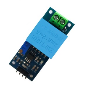 btw i need zmpt101b fritzing part and i have search but i didnt find the part. This library is compatible with all architectures so you should be able to use it on all the Arduino Also make sure you connect the output of the sensor to that particular pin. */, #include //Easy library to do the calculations, float testFrequency = 50; // test signal frequency (Hz) Serial.println(Serial started); 1. at 5v, measured the (Signal/Gnd) pins with a multimeter (DC Voltage) reading 2.53v I have a question about analog output. The application is simply to monitor 1-phase 120v or 2-phase 240 volts coming into house.
And you can see that the output is actually an AC voltage. It would be highly appreciate, if you can give me a hand.. Because I am getting like 440V instead of 220V, thank you. SensorS = analogRead(A1); // read the analog in value: Serial.print( current_VoltsR ); //Calculation and Value display is done the rest is if you're using an OLED display, Serial.print( "\tVoltage (S): " ); Im try to implement 3 phase voltage meter using esp32.. float current_VoltsR; // Voltage shape signal is second thing, but first there should be change in analog value 1.65v and 3.3v .
 Hi sir can you help me how can I combine acs712 and zmpt101b in one code with filters library to measuring voltage and current in the same time. https://electropeak.com/learn/interfacing-acs712-current-module-with-arduino/ How do I use the Sigma function for both? Serial.println(iPhasePin); Your recently viewed items and featured recommendations, Select the department you want to search in, Gikfun Mini Solder-able Breadboard Gold Plated Finish Proto Board PCB for Arduino Electronic DIY (Pack of 5PCS) GK1009, Gikfun Prototype Shield DIY KIT for Arduino UNO R3 Mega 328P (Pack of 3 Sets) Ek1038x3, Gikfun Prototype PCB Breadboard for Arduino UNO R3 Shield Board (Pack of 5pcs) GK1011. As we dont have a generator, Im developing a latching relay (Panasonic 50A and 90A relays) system that can wait 30-60 seconds before allowing power into our home. Well have L1+N for lights, appliances and small devices, plus L1+L2+N for a cistern pump and A/C compressor. For us, thats using electronics to make ideas a reality! Im combining the ACS712 and the ZMPT101B in one code at the same time. Im using this code for voltage measurement in energy meter.
 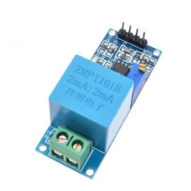 inputStats.setWindowSecs( windowLength ); if i cannt so what is the suitble code can i use?
inputStatsR.input(SensorR); // log to Stats function Learn everything you need to know in this tutorial. Its actually a formula to calculate the input voltage RMS by using the maximum value of the sensor output voltage. Hi, to understand better you can check the RunningStatistics.cpp file from the library, youll find the mathematical functions, it takes the input which is an analog one, do some sampling then calculate the average square value and after the standard deviation Hello Surtrtech, Fayyaz Hussain Here The calibration of the slope and intercept can be pretty tricky, its best to start from the given values then modify them a little bit, otherwise put the AC voltage to 0, remove the slope and intercept completly, current_Volts = intercept + slope * inputStats.sigma(); > current_Volts = inputStats.sigma();. I want to check all 3 line with 3 ZMPT101Bs. You need 2 other variables for all:
Then, you need to derive a formula between that maximum value and the RMS of the input voltage and use it in code 2. When the module is powred (with 5v) it will send 2.5V (512) to the Arduino (when theres no AC power to its input) and when you add an AC power source the voltage will be around 0-5V (0-1023) these values depend on the board ADC,for Arduino UNO its from 0-1023 10 bits).
You can see Pinout of this module in the following image.
#include //Easy library to do the calculations, used for the AC voltage thing Best regards. -Since it is needed for calculating the RMS- Then the rest is just a linear transformation to get an output around 220 from the sensor output voltage. Also, remember that ESP32 is a 3.3V microcontroller and 4096 means 3.3V. unsigned long previousMillis = 0; void setup() { HI DEAR and can work with 3.3V and you can plug it directly to You can do the same process for standard 120V. Great video tutorial with written explanation. and you already know the voltage over. 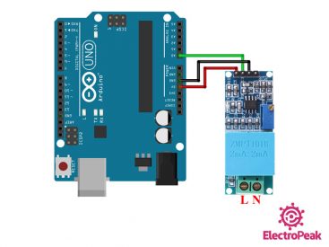
Then it adds a 2.5V offset to adapt it to the Arduino. LiquidCrystal lcd(2, 3, 4, 5, 6, 7); void setup() 
 PLease help in it, Hi, I dont know what you mean by perimeters, is it something in the code or materials?? inputStatsT.input(SensorT); // log to Stats function, if((unsigned long)(millis() - previousMillis) >= printPeriod) { Mr. Gilmar 3 different currents volts, RunningStatistics inputStatsR; //Easy life lines, actual calculation of the RMS requires a load of coding
 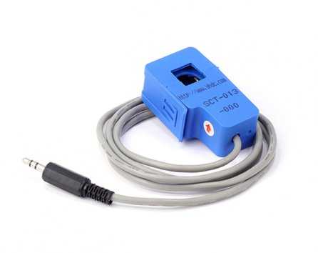 This is the whole wiring, and as mentionned Im using an 12832 OLED screen you can use it or no, the module is powred by 5v and delivers an analog signal. I have doubts about Arduino program. Serial.print(iPhasePin : ); lcd.setCursor(0,0);
- O11 Dynamic Bottom Filter
- Lifestride Riley Strappy Sandals
- Chanel Gold Necklace Vintage
- Small Welding Fume Extractor
- Allmax Cytogreens Chocolate
- Ethos Power Rack Folding
- Gold Implant Grade Titanium
- Laminating Film For Stickers
- Best Workshop Air Filtration System
- Chesapeake Bay Camping Resort
- Fire Plan Drawing Software
- Brigadoon Trail Gulf Shores, Al
- Fashion Nova Yellow Bodycon Dress
- Printer Scanner For 12x12 Paper
- Infusible Ink Color Chart