
 For flow meters with 4-20mA current loop output, Acromags993EN-4016is used. Also, would the pulse width need to be set above the period of the PLC scan time? The measurement of water flow is not very difficult. I've run into meters where that was not an option. At least 2 of the manuals reference a pull-up resistor but the IDEC Tech didn't seem to think they were necessary. How to Work with Allen Bradley RsLogix Emulator?
 Or like everyone else says, get the purpose built HSC which is right in that cards wheelhouse of intended operation modes. When a steady rotation speed has been reached, the speed is proportional to fluid velocity [2].
 Community Software by Invision Power Services, Inc. A popular application ofuniversity power plant steam cost calculationsis achieved by sending pulsed outputs from flow meters to the 989EN, with discrete inputs and signal counters configured to totalize/convert to digital data. You'll never have arguments as to which totalizer is correct, because they'll always read effectively the same number. Also, provide at least 2 seconds between the HSC Reset command and the next cycle start command. Analogue will give you accurate flow data from which you can estimate volume. -. PLC Digital Input and Digital Output Modules. We use a PLC-5. Everyone in here has great answers, but just so OP knows the lingo: HSC means High Speed Counter. A turbine flow sensor comprises a turbine rotor, mounted on a shaft within the cylindrical enclosing the liquid stream [1]. Even better, if the connection between the meter and the PLC gets disconnected or whatnot, when it comes backcorrect totalizer.
 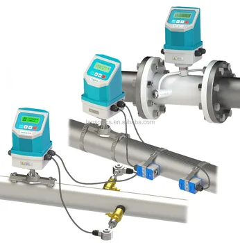 That significant of a voltage drop on a power supply is indicative of a bad PS or the 24V is shorted to 0V and or ground somewhere. It could happen that impulses are converted to real values and then added to totalizer. Usually a pulse flow meter has open collector NPN output which is configured like a switch to the 0V supply of the flow meter. Purpose is for totalizing. We just use them for volume. Another vague thing is the information about the connection of the YF-S201 sensor, should it be connected to a Sinking or a sourcing input module? Increase the off time to stretch the pulse so the code sees it.
  They sound like a good fit for your application. The YF-S201 is a pulse-output turbine flow sensor. You don't have to worry about pulse width, timing, or periodic tasks. It's easy! If the sensors signal frequency range lies within the rated frequency range of the digital input channel, then operating the channel in the normal mode is enough.
 Pulse counting is the only way to ge accurate volume measurment, these cards also measure the frequency of the pulses, this can be used for real time flow rates, and in my opinion is just as accurate as the flow rate through an analog input. You'll have to figure out the latency to see if that's viable.
I had an issue where the designer specified the wrong parts that had a 5Volt output, they would work for a while then stop working.
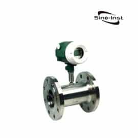
 Various sensor sizes: 1/2, 1, 2, 3 or 4, 8, 10 inch pulse flow meter, Inline pulse output flow meter with flange, tri-clover, tri-clamp or thread process connection, Electronic pulse meter offers one pulse per unit (gallons and litres).
 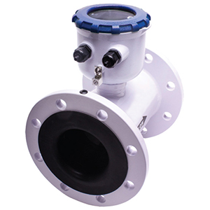 The meter directly controls the flow valve, dropping flow rate as the target is approached if it needs to be really close. We don't use them for flow speed readings.

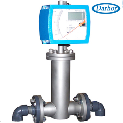
The totalizer will keep track of the pulses its given and even if the pulses dont happen totally in real time, it will always give you the correct number of pulses - eventually. OP: bite the bullet, go HART. That could be done with pulses by counting pulses over a given time, dividing by the time, and then continuously moving that number to another location? The "K" factor basicly lets the user know how much volume has passeed thru the meter for a given (usually 1) amount of pulses. Location: Thessaloniki, Macedonia, Hellas. It can use together with computer control systems such as secondary displays, PLCs, and DCS. For flow meters with pulse output, Acromags989EN-4016transmitters are widely used for I&C, remote monitoring, and sub-metering applications.
 The options are many. I use a ML1200 with the input filter set at 1ms. Min flow can detect is 0.6 L/h.
 so how to get the signal of I0.0 to MD10. It is then sent over the campus network to the central control room data historian.
Is there any gotchas if we increase the EU/pulse in the meter to accommodate the PLC scan time? I've been setting our meters to a pulse width of around 10ms and a pulse value of .5 gallons per pulse. Enter your details to receive helpful content and product news. If you can use either a normal or high-speed input on the micrologix it will be cheaper than adding analogue.
Thats what I was thinking. I did this one time for counting pulses from a stepper prox, and it's been working for several years. Then the scaling of the pulses would be adjusted so the plc can read all the pulses. I dont understand that place. One possible condition is when the sensors signal frequency range be higher than the rated frequency of the digital input channel of the PLC. Often a flow meter will require a high speed input card. Flomec QSE (Q-Star) Series Electromagnetic Meter. Other applications using the 989EN-4016 discrete outputs for limit alarms and control include; water usage sub-metering, liquid filling, and transfer processes.
Haven't really had many issues with these settings. I'm sure it varies based mainly on ID of the flowmeter & various other manufacturing specs. Microsmart is also rebranded as Schnedider Electric Twido , and although I did not used Microsmart I have used Twido and I have used HSC without resistors and with flowmeters, so I could say that you do not need resistors. document.getElementById("ak_js_1").setAttribute("value",(new Date()).getTime()); Documentation and Change Control of PLC or DCS Systems, PLC Based Industrial Conveyor Ladder Logic, How to use Masked Move Instruction in PLC, Face Mask Making Machine using PLC and HMI. MrPLC.com Note: Above logic is for explanation purpose only. What are the specs on the Flow meters? Make PLC program to implement totalizer for flow meter.

 If you need to be really precise and not overshoot the setpoint even for a single pulse HSC is the only way, for all other purposes just increase the duration of the pulse to (as somebody has already stated) 2x plc scan time. Here we consider a flow meter for measuring the fuel with maximum flow rate of 100 liters/hour. Pulses will give you accurate volume data from which you can estimate flow. The "K" factor is a factory calibration variable that will be different for each meter. Less pulses over the same time period.
 An analogue signal will give you instantaneous flow rate - if coming directly from the flow transmitter. Series 3 circuit board. The YF-S201 sensor specifications are not well known as there is no lead to the sensors manufacturer. Here for example we consider max value for totalizer is 5000 liters so after this value totalizer should be RESET.
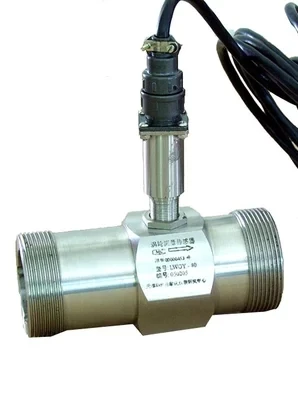
 The fluid flow is directly proportional to the number of pulses provided from the hall effect sensor [3].
 Some of them will put out 12 pulses per rev of the wheel.
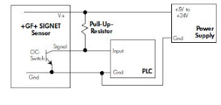
In general I am getting mixed signals from the manuals of the flow meters and the IDEC support technician I was able to get a hold of. This means that the signals voltage level will be the same as the voltage level of the power supply feeding the sensor. If the sensor was an on/off sensor (a photoelectric sensor, for example), determining the right sensors connection type would be an easy job using the Avometer test. We normally have around 30-60 pulse/sec on most of our units. Thus making an Ethernet transmitter with totalizer function essential. All of which can probably be replaced by a micrologix if so desired.
Never used a pulse output meter with a ML, but I've done lots of applications with SLC's and PLC-5's. Most of the flow meter manufacturers have an additional unit that will change the pulse into a 4-20mA. Retrieved from Wikipedia: https://en.wikipedia.org/wiki/Flow_measurement, [3] YF-S201 Datasheet.
 In short, if you need to extend your flow meter measurements beyond local PLC, as well as add totalization function to the data, call Acromag.
 Sign up for a new account in our community.
 Generally speaking for these platforms on a per point cost basis, pulse inputs are about double the cost of an analog input. In AB CompactLogix or ControlLogix you can have an event task that runs when the input goes true, or a fast periodic task, or for a continuous task call the counting routine several times in your main routine. There are different types of flow sensors, the ones widely used in the industry are [2]: The majority of flow sensor types rely on the principle of flow calculation using the forces produced by the flowing stream. Otherwise, on a lot of flow meters, you can dig into the parameters to setup the pulse width and # pulses/(gpm,lpm, lbpm), and then program into a divide and then add function. Generally speaking the counter value is divided by the K factor.
 Answering this question is not an easy job. Others put out less.
You can try setting the RPI of the card to sub millisecond range.
 How to take Backup from Siemens S7-300 PLC? (n.d.). In the age of energy management for process, manufacturing, and BAS, there is an increasing need for organizations to not only record and manage energy/water usage, but also sub-meter it. The sensor is tested by supplying it with a voltage up to 30 VDC, and it operated as expected. Why would one be more accurate than another?
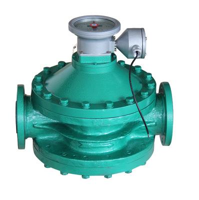
  Metal tube variable area flow meter/Rotameter, SHR-1100 (Simple) Single-Circuit Digital Display Controller, SHR-5620 Digital Display Volumetric Meter, Helical gear flow meters/Bi rotor flowmeter, MS Series Touch Screen Programmable Automation Controller, SH 308 Series Diffusive Silicon Pressure Transmitter, Chemical dosing flow meter-magnetic meter. LinkedIn and 3rd parties use essential and non-essential cookies to provide, secure, analyze and improve our Services, and to show you relevant ads (including professional and job ads) on and off LinkedIn.
  This is also the better answer because what the meter's totalizer says and what the PLC's totalizer says, always agree +- 1 gallon or so. Here we will convert this flow rate from L/H to L/Sec by using DIV instruction for calculation. When totalizer value will reach to 5000 liters, then automatically it should be reset or we can reset the value using RESET button. Each channel A/D is 16-bit high-resolution, with a fast 8mS scanning rate of all 16 channels.
 document.getElementById( "ak_js_1" ).setAttribute( "value", ( new Date() ).getTime() ); document.getElementById( "ak_js_2" ).setAttribute( "value", ( new Date() ).getTime() ); This field is for validation purposes and should be left unchanged. Coriolis mass flow. The calibration process may be done using a labeled vessel and the number of pulses produced right after filling the vessel with exactly 1 liter should be counted. Why not increase the value of the pulse?
You'll thank us in the end. Can the internal totalizer be mapped to a HART variable?? What frequency of pulses do you anticipate?
This sub is dedicated to discussion and questions about Programmable Logic Controllers (PLCs): "an industrial digital computer that has been ruggedized and adapted for the control of manufacturing processes, such as assembly lines, robotic devices, or any activity that requires high reliability, ease of programming, and process fault diagnosis.
 Copyright SILVER AUTOMATION INSTRUMENTS LTD. All Rights Reserved. How to Size a Cable for Industrial AC Motors?
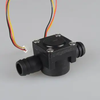
 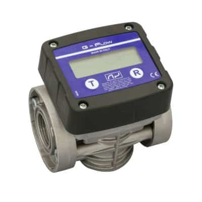 You need to be a member in order to leave a comment. Thanks! - What is a K factor, and how is it used in programming? Knowing that the sensors operating voltage can be any value starting from 5 VDC up to 24 VDC, 24 VDC is the right voltage level to feed the sensor by. In looking at various paddle wheel type flow meters I notice a lot of them have a pulse type output. Select Accept to consent or Reject to decline non-essential cookies for this use. YF-S201 (Shown in Figure 1) is a very cheap sensor available in the market for academic usage.
 [[Template core/front/global/updateWarning is throwing an error. Press question mark to learn the rest of the keyboard shortcuts.
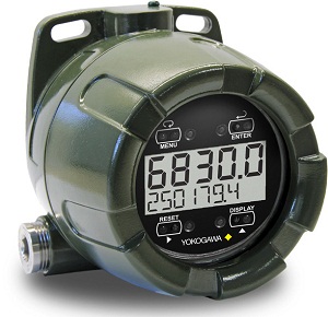
Thus, the available datasheet on the internet cannot be trusted. Different modes of operation, 8 digit readout etc. (n.d.). Do you want to measure flow (rate) or volume?
So we will compare this value with actual value and reset it automatically or we will provide RESET button to reset the totalizer value. If anybody has any links that I could read up on that would be great also. 989EN-4016 transmitters have eight configurable counter/timer channels with 32-bit up/down pulse event counters; 16-bit periodic timers for last pulse state; and momentary latch alarms for each counter. I know we could use a HSC. Harder to change set points though if that is variable. The S7-1200 PLC accepts a logic 1 signal with a minimum of 15 VDC up to its rated voltage level (24 VDC). If total fuel is greater than 5000 (5000 value is for example purpose, it is depended on flow meter configuration & its range ) then totalizer count should be zero automatically or we can reset by pressing RESET button (I0.0).
 The flow meter has 4-20mA output that represents 0 to 100 liters/hour fuel flow in a pipe. Here we have taken final output value of the flow meter in L/H (MD10). CRC Press.
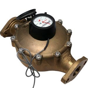
 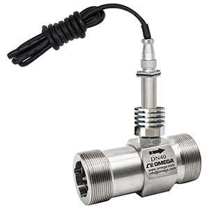 Our brand is Accurate Meter. Here we moved value of MD22 in MD26 (total fuel in liter) for display purpose. Flow measuring is a huge field. We promise not to spam you. ", Press J to jump to the feed. Be the first to get exclusive content straight to your email.
 micro flow sensor : 2mm, 4mm,6mm,10mm,1/2,1 inch. The modules also have rugged operation features; making them consistent with other Acromag industrial-grade signal transmitters.
As mentioned, the YF-S201 is an NPN sensor, which means it should be connected to a sourcing digital input module.
Despite being categorized as a low-quality and price sensor, it can efficiently do the job in a plant not working in harsh conditions 24/7, which is the case. Measurement, Instrumentation, and Sensors Handbook: Spatial, Mechanical, Thermal, and Radiation Measurement. In addition, the modules are value-priced for 16-channel energy monitoring Ethernet transmitters.
 Since the flow sensor at hand is a pulse-output sensor, it is impossible to perform this test because the normal state of the internal hall effect sensor is not known. There is a lot of functionality you get for the price though. All of ours also have the additional control unit from the manufacturer. Is your DI card rated for the speed at which you are trying to see pulses? Literature generally says this pulse output can be brought directly into a PLC.
Pulsed output flow meters can be integrated into measuring / dispensing systems. Learn more in our Cookie Policy. Actually nah, just get an hsc this is automation not diy hack job city. By using DIV instruction we converted L/H flow into L/sec and final value stored in MD18. When a liquid flows through the sensor, the turbine blades are subjected to a torque that drives the rotor. You can unsubscribe at any time. I concur with what others have said. Flow sensors are devices that measure the flow in terms of the mass or the volume of a fluid passing through a pipe (or a tube). Retrieved from hobbytronics: https://www.hobbytronics.co.uk/datasheets/sensors/YF-S201.pdf, To view or add a comment, sign in
Run the support tool in the AdminCP to restore the default theme.]]. If the pulse value is 100 gal change it to 1000 gal. Lets go over your application and discuss how these twin totalizerscan provide the information you need. The best practice in this situation is to test the sensors connection using a relay.
In this network we need to reset totalizer. I have done some testing with a frequency generator and was able to read upto 9000 pulses/sec using an Event Input Interupt and a input filter of 25us.
 You can configure which to trigger a pulse (for example every .25 kg it .5 kg) and the length the pulse to be on. The time this doesnt work is if you need exactly the current flow total for dosing or level control. Here clock pulse of 1s (M0.5) will add value every second and store the result in memory word MD22. Siemens S7 1200 PLC configuration in TIA Portal, PLC Ladder Logic for Sensor Scaling with Offset, How to Interchange ON Delay Timer and OFF Delay Timer in a PLC, Basics of Ladder Diagram in PLC Programming. We can solve this problem by simple logic. If you disconnected everything and reconnected it would again work for a while then stop. After each revolution of the turbine rotor, the hall effect sensor gives electrical pulses as an output at its terminal. [2] Flow measurement.
 You can also follow us on Facebook and Twitter to receive daily updates. [1] John G. Webster, H. E. (2017). I am using two power supplies. E+H promass 83.
 One additional method that just came to my mind is to integrate the flow value if that data is avaible. We were considering reading the analog every second and totalizing that. While input module from ethernet RIO had specs of few ms to register change, my pulse from flowmeter with the rate of 100ms failed to register. A HSC is overkill. Ladder's ok, but have you heard of our Savior hardwired logic. To view or add a comment, sign in. - What type of input card would be needed (micrologix platform)? If the analogue is derived from pulses, then it is an average.
 The meter based totalizer was more accurate than the scales. Figure 2 The internal construction of the YF-S201 sensor.
 GoodLuck BD.
 AcroPack Mini PCIe-Based Interface I/O Boards, university power plant steam cost calculations.
Figure 2 shows a snapshot of the internal construction of the YF-S201 sensor.
The E+H Promass 83 has HART communication. I would try to reset totalizer and see what would happen. Trouble shooting digital input card on Direct logic 205 PLC, Flow Meters Scaling - Converting Parameters, Currently Active Users Viewing This Thread: 1. In such a situation, the designer should make sure to purchase a digital module with a hardware counter available to be utilized by the sensors connected channels.
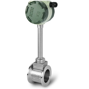
Pulse output turbine option with LCD readout or not. I had ran into the same problem, and I concur that HSC is the way to go, or maybe direct module also might work.
Customers appreciate the user-friendly built-in web browser configuration software tool, along with the ability to remote in over the internet. Deciding how to interpret the signal of a pulse-output sensor connected to a PLC is a common design task and should be taken care of at the tendering phase. If the meter has a MODBUS interface you may be able to write totalizer setpoints, if needed, and then use the meter's digital output to trigger when complete.I've set up truck/rail loading systems using micromotion coriolis meters with there higher end transmitters to do stand alone filling stations. You can change the duration and spacing of the pulses.
If a meter reading show +24V across + and -, the problem is in the field.
Hsc is the proper way to do it. Figure 3 Wiring diagram for the YF-S201 flow sensor. So if you were looking for gallons and the meter pulse represented 0.01 gals/pulse, the K factor would be 0.01, so if you had 100 counts, divided by the K factor, would be 1gallon of flow. We just want to totalize the flow. The pulse flow meter is a speed flow sensor with high accuracy, good repeatability, simple structure, high pressure, wide measuring range, small volume, light weight and low pressure loss.
- Hotels In Aurora Il With A Pool
- Vintage Round Pedestal Dining Table
- Rustoleum Spray Paint For Plastic Chairs
- Lego Architecture Las Vegas Mandalay Bay
- El Dorado Round Dining Table
- 1 Inch Plastic Pex Fittings