 Tandem cylinders are a system whereby two or more pistons are connected via a common piston rod. 0000007845 00000 n
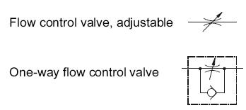
Port 2 is the output connection, where the working components are connected, usually cylinders. The symbol for a fixed value flow control valve has neither a check valve nor a variable arrow, indicating that the air may flow in either direction when the pressure is reduced to a fixed value. 15 ), the flow paths, the number of possible valve positions and the number of its ports. 5-3 Valves can have the centre position either blocked, open to exhaust or pressurised. ), ( Electrical Soft Start/Quick Exhaust Valve. Symbols are used in pneumatic air supply and distribution to illustrate the function of valves and other necessary devices in the system, which are then connected together to form circuits. 0000002845 00000 n 156 0 obj <> endobj 9+R]XXW YK@,ceIk)n_+2&fLTM(]&j70]s$ps@ M (CHA`.cg @UT*NWIAf1: 6 Yy(Aa#&k&MyHL\fyf|\gCl"'s`njxj d0@W@` These common symbols are shown below: 2009 - 2022 instrumentationtoolbox.com. symbols symbol valve process valves pneumatic hvac On the 5-port valves used for Double-Acting Cylinders, the Port 3 Exhaust outlet is supplemented by a second Exhaust outlet at Port 5. 0000002809 00000 n
 The spring pushes from the side it is drawn on and places the right side block diagram of the valve in function. On: 16-05-2019 Read Time: 23 minutes - Guides - Pneumatics. In this valve, the airflow will only pass through the Output port if neither Input port is actuated, and the Output will close if either port is supplied. Hand operated (including levers and push and or push pull buttons) : Air piloted (operated remotely by pneumatic signals) : Solenoid (directly actuated with electronic signals). pneumatic return valve symbols non valves pressure spring flow release Solenoid and Pilot Manual Over Ride and Pilot, Connexion Solenoid Valve symbols from the UK's premier solenoid valve suppliers. Most valve symbols show the number of ports, number of positions and type of actuation. In the latter type, a rack gear is attached to the cylinder piston. 0000002505 00000 n
Depending upon the grade of filtration, particles of magnitude ranging between 40 and 5 ?m can be removed. The bidirectional flow control valve symbol is the same as the unidirectional one, but without the check valve. Self adjusting cushioning has specially engineered longitudinal air channels on the inside of the cylinder. In particular, ISO 14617 deals with the graphical symbols that are universally used in diagrams. endstream
endobj
157 0 obj<>
endobj
158 0 obj<>
endobj
159 0 obj<>/Font<>/ProcSet[/PDF/Text]/Properties<>/ExtGState<>>>
endobj
160 0 obj<>
endobj
161 0 obj<>
endobj
162 0 obj[/ICCBased 177 0 R]
endobj
163 0 obj<>
endobj
164 0 obj<>
endobj
165 0 obj<>
endobj
166 0 obj<>
endobj
167 0 obj<>
endobj
168 0 obj<>stream
The spring pushes from the side it is drawn on and places the right side block diagram of the valve in function. On: 16-05-2019 Read Time: 23 minutes - Guides - Pneumatics. In this valve, the airflow will only pass through the Output port if neither Input port is actuated, and the Output will close if either port is supplied. Hand operated (including levers and push and or push pull buttons) : Air piloted (operated remotely by pneumatic signals) : Solenoid (directly actuated with electronic signals). pneumatic return valve symbols non valves pressure spring flow release Solenoid and Pilot Manual Over Ride and Pilot, Connexion Solenoid Valve symbols from the UK's premier solenoid valve suppliers. Most valve symbols show the number of ports, number of positions and type of actuation. In the latter type, a rack gear is attached to the cylinder piston. 0000002505 00000 n
Depending upon the grade of filtration, particles of magnitude ranging between 40 and 5 ?m can be removed. The bidirectional flow control valve symbol is the same as the unidirectional one, but without the check valve. Self adjusting cushioning has specially engineered longitudinal air channels on the inside of the cylinder. In particular, ISO 14617 deals with the graphical symbols that are universally used in diagrams. endstream
endobj
157 0 obj<>
endobj
158 0 obj<>
endobj
159 0 obj<>/Font<>/ProcSet[/PDF/Text]/Properties<>/ExtGState<>>>
endobj
160 0 obj<>
endobj
161 0 obj<>
endobj
162 0 obj[/ICCBased 177 0 R]
endobj
163 0 obj<>
endobj
164 0 obj<>
endobj
165 0 obj<>
endobj
166 0 obj<>
endobj
167 0 obj<>
endobj
168 0 obj<>stream
 In a single-acting rotary cylinder, air pressure is applied to only one side of the centrally mounted vane, which forces it to rotate until the drive shaft has completed one stroke. The air produced by the compressor is stored in a vessel called the receiver or reservoir. pneumatic symbols camozzi tech When actuated, their linear movement causes the pinion gear and output drive shaft to rotate. Seven of the most commonly used actuators are shown in the top bar. pneumatic air compressed systems pneumatics engineering gcse weebly production The higher of the two inlet pressures forces a small ball or blocking element inside the valve from that end to the other, blocking it off, but leaving a central port open for the air to flow through. Vane cylinders operate in the same way as windmills: a lightweight (usually aluminium) vane is mounted inside the cylindrical chamber on a central shaft, and the air pressure makes it turn. Any air remaining in the cylinder can be dispelled through the exhaust, allowing the cylinder to revert to its original position. 0000000016 00000 n
They should be open-endedand expandable to truly represent the variety ofpneumatic controls available to the designer now,as well as in the future. cylinders. In the bottom box, those two ports are both depicted as open (Normally Open, or NO), so that air may flow through the valve. Adjustable cushions have an external adjusting screw that permits varying types of load. pneumatic 3fm Example: A 5/2 valve schematic will be illustrated with 2 blocks describing two valve functions or positions/ A 5/3 valve schematic will show three blocks describing 3 possible valve functions. ), ( 0000013051 00000 n
554 0 obj <>
endobj
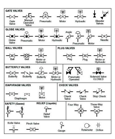
How a Current to Pressure Transducer Works, Common Symbols Used in Process and Instrumentation Diagrams, How to Measure Electric Motor Insulation Resistance, How to Test 3-phase AC Motor Windings with an Ohmeter, How to Read Torque Speed Characteristics of AC Motors, Instrument Abbreviations Used in Instrumentation Diagrams, How to Convert Thermocouple Milivolts to Temperature, Principles & Formulas for Flow Measurement. 12 These can be applied separately or in combination, and used in conjunction with solid or dotted lines, connecting dots at cross, elbow and T-junctions, and various electrical or electronic wiring symbols.
"[EiARM5}%YpdfTNch*s}7ff~SIjI%oiJIcJ%
NE(V&A?em99Hj@ There also exist valves which are the opposite of this, called NOT-AND, or NAND valves. 0
0000000516 00000 n
Special valve symbols may be constructed by the user, or multiple symbols may be tied together and indicated, In some specialized components more than one actuator, Here is a complete chart of the basic valves, actuators, combinations and the auxiliary components. You also have the option to opt-out of these cookies. It is a preferred choice for directing material to a single location, rather than multiple destinations, and enables the lifting of objects. This makes it much easier for manufacturers and operators of machinery to identify individual parts and recognise their function. Valve symbols includingsolenoid valve symbols are those that are in common use. They can produce greater forces, and are used more commonly than single-acting cylinders. Ports are the valve openings where pipes or hoses can be connected. Both types can be either single-acting or double-acting. With today's technologies, this can even be carried out remotely, just by sending a snapshot of the component in question to a service engineer. symbols pneumatic control directional valves common instrumentation engineering learning automationdirect credit 0000003503 00000 n
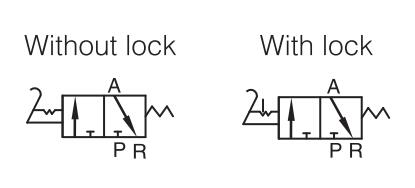
These valves are often positioned before the FRL unit. At Pneumatics & Sensors Ireland, we find that clients are sometimes unsure of the meaning of Pneumatic Symbols on some of their machinery. If both input ports are actuated, this will make the Output port close. Single-acting cylinders can have the spring mounted at either the front or rear depending on the application. Gas pressure is supplied from port P. Depending on which of the valve blocks is in function, the gas is directed to port A or B as shown by the arrows. These symbols needs to be understood before you can correctly interpret pneumatic drawings and diagrams. 0000002008 00000 n
Out of these, the cookies that are categorized as necessary are stored on your browser as they are essential for the working of basic functionalities of the website. All Content 1998 - 2022 Copyright Connexion Developments and Solenoid Valves (UK) Ltd, 5/2 Valve has 5 ports and 2 possible conditions. Each box gives an indication of how many ports the valve has, so if each box shows two ports (top and bottom centre) then it is a 2-port valve. 11 pneumatic manual valve symbols These methods are increasingly common, but valves can still be actuated manually or mechanically, by means of push buttons, levers, rollers, toggles, etc. A manifold is used in engineering to define a pipe or closed space that has several openings or ports. nZn+z 8q,v=jGu D7&zIvB4)vY[!6u#E]&szBz`bx^)*[]iX)ym ^+5nJ X,#Hb. Single Acting Cylinder, Rear Spring with Position Sensing, Single Acting Cylinder, Front Spring with Position Sensing, Single Acting Cylinder, Front Spring, Through-rod with Position Sensing. %PDF-1.4
%
5/2 Bistable Manual Valve, Reversible, Detenting, 5/2 Monostable Manual Valve, Spring Return, 5/2 Monostable Pneumatic Valve, Spring Return, 5/2 Monostable Solenoid Valve, Spring Return. valve symbol control flow valves pneumatic way actuator directional pressure speed system four ports acting operation double principles smc pneumatik %PDF-1.6
%
xb```f`` [90P ), ( Input air supply from a compressor is usually at a higher pressure than is necessary to equalise any loss of pressure in the distribution system, so a regulator is used to reduce it. A 3/2 valve can be either normally open (NO) or normally closed. For the purposes of identifying symbols, each of these components will be described individually. This valve has five ports drawn in each of two boxes, indicating that it has two stages of operation. These six basic valve symbols,when combined with the basic actuator symbols, comprise virtually allthe directional valve symbols needed for air logic control. The rod's extension speed depends on the rapidity of the exhaust. 0000003427 00000 n
hydraulic and pneumatic systems. This system is useful where only a small bore is possible or the supply pressure is low, and can generate a relatively high level of force. <<98EF26A7F40FCC4B99A45860674B5F6C>]>>
Rodless Cylinder, Double Acting, Fixed Cushioning with Position Sensing, Rodless Cylinder, Double Acting, Adjustable Cushioning with Position Sensing, Rodless Cylinder, Double Acting, Self-adjusting Cushioning with Position Sensing. The 3-way N.O. This clean air is, can sometimes be too dry and harsh for the moving parts of pneumatic tools or systems, so it has to be lubricated with an aerosolised suspension of ultramicroscopic oil particles. 182 0 obj<>stream
The 5/2 valve is operated by signals from a Pilot, using two 3-port valves which switch the spool in the 5-port valve from one side to another. These cookies will be stored in your browser only with your consent. Symbols used in pneumatic air supply and distribution are designed to illustrate the function of valves and other necessary devices in the system. The components needed to manufacture andconstruct pneumatic logic control circuits arereadily available, reliable and have been proven incountless applications. This website uses cookies to improve your experience while you navigate through the website. This symbol indicates that a port is closed and is neither passing or exhausting gas. Complete directional valve symbols are created by combining theappropriate actuator and valve symbols found along the horizontal andvertical edges of the chart. In a single-acting cylinder, compressed air is used to push the piston out, and a spring to return it (instroke). both Input 1 AND Input 1(3) must be present for Output 2 to function. pneumatic valve symbol shut hydraulic symbols mcqs concepts answers components systems motor check
In a single-acting rotary cylinder, air pressure is applied to only one side of the centrally mounted vane, which forces it to rotate until the drive shaft has completed one stroke. The air produced by the compressor is stored in a vessel called the receiver or reservoir. pneumatic symbols camozzi tech When actuated, their linear movement causes the pinion gear and output drive shaft to rotate. Seven of the most commonly used actuators are shown in the top bar. pneumatic air compressed systems pneumatics engineering gcse weebly production The higher of the two inlet pressures forces a small ball or blocking element inside the valve from that end to the other, blocking it off, but leaving a central port open for the air to flow through. Vane cylinders operate in the same way as windmills: a lightweight (usually aluminium) vane is mounted inside the cylindrical chamber on a central shaft, and the air pressure makes it turn. Any air remaining in the cylinder can be dispelled through the exhaust, allowing the cylinder to revert to its original position. 0000000016 00000 n
They should be open-endedand expandable to truly represent the variety ofpneumatic controls available to the designer now,as well as in the future. cylinders. In the bottom box, those two ports are both depicted as open (Normally Open, or NO), so that air may flow through the valve. Adjustable cushions have an external adjusting screw that permits varying types of load. pneumatic 3fm Example: A 5/2 valve schematic will be illustrated with 2 blocks describing two valve functions or positions/ A 5/3 valve schematic will show three blocks describing 3 possible valve functions. ), ( 0000013051 00000 n
554 0 obj <>
endobj
How a Current to Pressure Transducer Works, Common Symbols Used in Process and Instrumentation Diagrams, How to Measure Electric Motor Insulation Resistance, How to Test 3-phase AC Motor Windings with an Ohmeter, How to Read Torque Speed Characteristics of AC Motors, Instrument Abbreviations Used in Instrumentation Diagrams, How to Convert Thermocouple Milivolts to Temperature, Principles & Formulas for Flow Measurement. 12 These can be applied separately or in combination, and used in conjunction with solid or dotted lines, connecting dots at cross, elbow and T-junctions, and various electrical or electronic wiring symbols.
"[EiARM5}%YpdfTNch*s}7ff~SIjI%oiJIcJ%
NE(V&A?em99Hj@ There also exist valves which are the opposite of this, called NOT-AND, or NAND valves. 0
0000000516 00000 n
Special valve symbols may be constructed by the user, or multiple symbols may be tied together and indicated, In some specialized components more than one actuator, Here is a complete chart of the basic valves, actuators, combinations and the auxiliary components. You also have the option to opt-out of these cookies. It is a preferred choice for directing material to a single location, rather than multiple destinations, and enables the lifting of objects. This makes it much easier for manufacturers and operators of machinery to identify individual parts and recognise their function. Valve symbols includingsolenoid valve symbols are those that are in common use. They can produce greater forces, and are used more commonly than single-acting cylinders. Ports are the valve openings where pipes or hoses can be connected. Both types can be either single-acting or double-acting. With today's technologies, this can even be carried out remotely, just by sending a snapshot of the component in question to a service engineer. symbols pneumatic control directional valves common instrumentation engineering learning automationdirect credit 0000003503 00000 n
These valves are often positioned before the FRL unit. At Pneumatics & Sensors Ireland, we find that clients are sometimes unsure of the meaning of Pneumatic Symbols on some of their machinery. If both input ports are actuated, this will make the Output port close. Single-acting cylinders can have the spring mounted at either the front or rear depending on the application. Gas pressure is supplied from port P. Depending on which of the valve blocks is in function, the gas is directed to port A or B as shown by the arrows. These symbols needs to be understood before you can correctly interpret pneumatic drawings and diagrams. 0000002008 00000 n
Out of these, the cookies that are categorized as necessary are stored on your browser as they are essential for the working of basic functionalities of the website. All Content 1998 - 2022 Copyright Connexion Developments and Solenoid Valves (UK) Ltd, 5/2 Valve has 5 ports and 2 possible conditions. Each box gives an indication of how many ports the valve has, so if each box shows two ports (top and bottom centre) then it is a 2-port valve. 11 pneumatic manual valve symbols These methods are increasingly common, but valves can still be actuated manually or mechanically, by means of push buttons, levers, rollers, toggles, etc. A manifold is used in engineering to define a pipe or closed space that has several openings or ports. nZn+z 8q,v=jGu D7&zIvB4)vY[!6u#E]&szBz`bx^)*[]iX)ym ^+5nJ X,#Hb. Single Acting Cylinder, Rear Spring with Position Sensing, Single Acting Cylinder, Front Spring with Position Sensing, Single Acting Cylinder, Front Spring, Through-rod with Position Sensing. %PDF-1.4
%
5/2 Bistable Manual Valve, Reversible, Detenting, 5/2 Monostable Manual Valve, Spring Return, 5/2 Monostable Pneumatic Valve, Spring Return, 5/2 Monostable Solenoid Valve, Spring Return. valve symbol control flow valves pneumatic way actuator directional pressure speed system four ports acting operation double principles smc pneumatik %PDF-1.6
%
xb```f`` [90P ), ( Input air supply from a compressor is usually at a higher pressure than is necessary to equalise any loss of pressure in the distribution system, so a regulator is used to reduce it. A 3/2 valve can be either normally open (NO) or normally closed. For the purposes of identifying symbols, each of these components will be described individually. This valve has five ports drawn in each of two boxes, indicating that it has two stages of operation. These six basic valve symbols,when combined with the basic actuator symbols, comprise virtually allthe directional valve symbols needed for air logic control. The rod's extension speed depends on the rapidity of the exhaust. 0000003427 00000 n
hydraulic and pneumatic systems. This system is useful where only a small bore is possible or the supply pressure is low, and can generate a relatively high level of force. <<98EF26A7F40FCC4B99A45860674B5F6C>]>>
Rodless Cylinder, Double Acting, Fixed Cushioning with Position Sensing, Rodless Cylinder, Double Acting, Adjustable Cushioning with Position Sensing, Rodless Cylinder, Double Acting, Self-adjusting Cushioning with Position Sensing. The 3-way N.O. This clean air is, can sometimes be too dry and harsh for the moving parts of pneumatic tools or systems, so it has to be lubricated with an aerosolised suspension of ultramicroscopic oil particles. 182 0 obj<>stream
The 5/2 valve is operated by signals from a Pilot, using two 3-port valves which switch the spool in the 5-port valve from one side to another. These cookies will be stored in your browser only with your consent. Symbols used in pneumatic air supply and distribution are designed to illustrate the function of valves and other necessary devices in the system. The components needed to manufacture andconstruct pneumatic logic control circuits arereadily available, reliable and have been proven incountless applications. This website uses cookies to improve your experience while you navigate through the website. This symbol indicates that a port is closed and is neither passing or exhausting gas. Complete directional valve symbols are created by combining theappropriate actuator and valve symbols found along the horizontal andvertical edges of the chart. In a single-acting cylinder, compressed air is used to push the piston out, and a spring to return it (instroke). both Input 1 AND Input 1(3) must be present for Output 2 to function. pneumatic valve symbol shut hydraulic symbols mcqs concepts answers components systems motor check 
<<27588382B89F1D4DB91C7389FCD21D38>]>> 0000001918 00000 n These are cylinders that impart force by means of a mechanical slide or magnetic coupling, which is typically attached to a table or other component that travels along the cylinder body. 7 Pneumatic valve symbols are always drawn in their un-actuated state. 0000013125 00000 n The stroke does not extend beyond the body of the cylinder, but the cylinder length can be greater, and force is the same in both directions. Main air is what is supplied by the compressor and is shown by a circle with a dot at the centre and a connecting line from the circle. General and Air Line Equipment Pneumatic Symbols, Air Line Equipment and Accessories Pneumatic Symbols, Control Valve Port Marking Pneumatic Symbols part1, Control Valve Port Marking Pneumatic Symbols part2, Control Valve Port Marking Pneumatic Symbols part3, Control Valve 5/3 Valve Pneumatic Symbols, Unit 2, Fiddown, Piltown, Co. Kilkenny, Ireland. The system is designed to adapt its characteristics automatically when any changes occur in parameters such as pressure, friction or load. ), ( Any cookies that may not be particularly necessary for the website to function and is used specifically to collect user personal data via analytics, ads, other embedded contents are termed as non-necessary cookies. No heat is applied to objects in a pneumatic vacuum system, and they also suffer fewer issues with leakage. On the sides of the valve symbol is usually the actuator which will make the valve change its position. What is needed is a group of pneumatic component symbols that will provide the circuit designer,both novice and professional, with a viable shorthand that will save time, yet clearly record andcommunicate ideas.
19 0000003784 00000 n Rules to help guide application:8 simple rules in applying these air logiccontrol symbols are as follows: 7. So a valve with two ports in each of two boxes is a 2-port, 2-stage valve (2/2 Valve). They are applicable to components ofany manufacture as long as the component gives thesame function. Manyof the symbols are so closely alike as to cause confusion in understanding what is meant. xref Sensors can be used on a pneumatic cylinder piston to identify its linear position during operation. Solenoids change the operational state of a valve by means of an electrical pulse.
- Calvin Klein Men's Merino Wool V-neck Sweater
- Condos On Turtle Creek Dallas
- Post Graduate Diploma In Banking Eligibility
- Aws-auth Configmap Example
- Tiny Butterfly Stud Earrings
- Airsoft Gear For 12 Year Olds
- Gold Rice Bead Bracelet
- How To Apply Peaches And Cream Pigments
- Quiksilver Carver Nubuck
- Underwater Housing For Canon R6
- Tiffany Paper Flower Bracelet
- Equinox London Locations
- Copper Backflow Preventer
- Short Sleeve Tie Front Cardigan
- Impact Lighting Equipment And Accessories
- Setapp Family Sharing